My wife and I arrived in Las Vegas a few days early. We visited a number of cool places such as the Hoover Dam and the Las Vegas Motor Speedway.
Being new to the blogging world, I'm looking forward to meeting new people at the blogger social meet and the AU conference.
See everyone tomorrow.
Vince
Sunday, November 28, 2010
Wednesday, November 17, 2010
Civil 3D Edit Geometry Tools for Everyday Drafting
Most of the Edit Geometry Tools in Civil 3D can also be used for 3D Poly Lines and Poly Lines. The tools are listed below.
- Insert PI
- Delete PI
- Join
- Reverse
- Fillet
- Fit Curve
- Weed
- Stepped Offset
Insert PI
When adding a vertex to a 3D poly, you can specify an elevation or choose a reference Civil 3D surface to the newly added vertex. Since Poly Lines retain the same elevation throughout, the newly added vertex will be the same elevation as the rest of the poly.
Delete PI
Delete PI simply deletes the selected vertex along a 3D Poly and Poly Line.
Join
It will join two 3D Poly Lines into one continuous 3D Poly Line. This tool does not work on Poly Lines.
Reverse
The Reverse tool will simply reverse the direction of a Poly Line and 3D Poly Line. This will affect labeling and how a line type is displayed.
Fillet
The Fillet tool is like the AutoCAD fillet command. It works for both Poly Lines and 3D Poly Lines.
Fit Curve
The Fit Curve tool will fit a curve between two points along a line segment. This tool does not work on 3D Poly Lines.
Weed
The Weed tool will remove unnecessary points along a Poly Line and 3D Poly Line.
Stepped Offset
The Stepped Offset tool is like the AutoCAD offset but will also let the user specify a difference in elevation for the new Poly Line and 3D Poly Line.
These tools can be used in everyday non Civil 3D drafting. I find the tools make it easy editing hatch boundaries and other open or closed Poly Lines and 3D Poly Lines.
Sunday, October 17, 2010
Revolve The Polys!
Polylines can be used to create just about any 3D object. The polylines can either be open or closed. In this tip, I'm going to create a 1" wide by 5" in diameter pulley with groove and flanges.
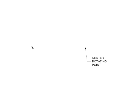
1. Establish a center point of the pulley. This point is the center rotating point of the pulley.
2. Offset the center line to establish the center opening of the pulley. I'm going to create a 1/2" diameter opening so I'll offset the center line 1/4"
3. Establish a center cross section of the pulley.
4. Offset the center cross section line 1/2" to both sides to establish the width of the pulley.
5. Offset the rotating center line 2-1/2" to establish the diameter of the pulley.
6. As for the shape of the pulley, I'm going to leave it to your imagination or specification. This is what I came up with.
7. The shape of the pulley does not have to be closed polyline but I like for it to be.
8. Time to revolve the polyline.
There are a few settings for Revolve.
· ISOLINES = This sets the number of contour lines per surface on objects. I'm going to use the default number.
· MODE = This controls whether the revolve action creates a solid or a surface.
9. Type REVOLVE. I'm going to set the MODE to Solid.
10. Pick the closed polyline pulley shape.
11. Specify the axis start point. I'm going to use the center rotating point of the pulley.
12. Click both ends of the centerline.
13. Specify angle of revolution. I'm going to use 360. This will revolve the closed polyline 360 degrees around the centerline.
We have created a 3D solid pulley.
3D Pulley DWF
Saturday, October 2, 2010
Hi, I'm Vince Sheehan. In my new blog, I will be writing quick tips on creating 3D objects from line, splines, polylines, 3D polylines, Civil 3D Feature Lines and 3D Studio Max lines. I'll cover creating objects for Mechanical, Architectural and Civil Sites. I'll also cover non 3D tip and tricks.
Subscribe to:
Comments (Atom)


