Showing posts with label GIS Data. Show all posts

Thursday, December 18, 2014

How to create a Civil 3D 2015 surface from an ESRI shape (shp) file.

In this tutorial, I’ll demonstrate how to create a Civil 3D 2015 surface from an ESRI shape (.shp) file. I believe this feature was introduced in Civil 3D 2014.

1. Create a new drawing containing Civil 3D surface styles.
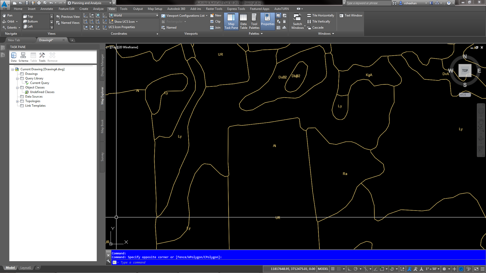
2. Zoom to the project location.
3. Set the project coordinate system. For this example, my project is located in Virginia so I’m using VA83-SF for a coordinate system code.
4. Click the Surfaces pull down on the Create Ground Data panel of the ribbon.
5. Click Create Surface from GIS Data to launch the wizzard.


6. Create Surface from GIS Data – Object Options.
     a. Type a name for the surface.
     b. The description is optional.
     c. Set the surface style.
     d. Set the layer to your standards.
     e. The render material is optional.
     f. Click Next.


7. Create Surface from GIS Data – Connect to Data.
     a. Click the SHP radio button.
     b. Click the box with the three dots and locate the shape file.
     c. Click the Login button.


8. Create Surface from GIS Data – Schema and Coordinates.
     a. Check the box next to the shape file name.
     b. Set the coordinate system for the data if needed and the drawing if you have not done so.
     c. Click Next.


9. Create Surface from GIS Data – Geospatial Query.
     a. Click the Window radio button.
     b. Click the selection button to the right.

     c. Select an area around the project limits. I usually select an area larger than the project.
     d. Click the Crossing radio button.
     e. Click Next.


10. Create Surface from GIS Data – Data Mapping.
     a. Not all GIS data is created equal. Look for Elevation or Elev. in the GIS Filed column.
     b. Click the Civil3D Property field to the right and select the data. My data is called Elevation.
     c. Click Finish


11. The finished object is a usable Civil 3D surface with elevations


Let me know if you have any questions.

Sunday, November 9, 2014

How to Import GIS Soils Data and Soil Type Labels into Civil 3D 2015

For this exercise, I have downloaded soils data from the United States Department of Agriculture web site. http://websoilsurvey.sc.egov.usda.gov

Importing the Soils Data
1.       Start a new drawing.
2.       Create a new Soils layer and Soils Label layer. I’m using  layer names for this exercise. C-SOIL-E and C-SOIL-IDEN-E.
3.       Change the drawing Coordinate System to the project location.
4.       Importing the Shape file (*.shp) data.
           a.       Type MAPIMPORT at the command line.
           b.      Change the file type to ESRI Shape file (*.shp).
           c.       Select the soilmu_a_aoi.shp file.
 
 
 5.       Change the following settings in the Import Dialog box.
           a.       Set the Drawing Layer..
           b.      Check “Import polygons as closed polylines”.
           c.       Add a data field by clicking in the data cell and the box on the right.
  

          d.      In the Attribute Data dialog box, click the “Create object data” radio button.
 
 
          e.      Click Ok to get back to the Import Dialog box.
          f.        Click Ok again to import the data.
          g.       Zoom extent to view the imported line work.
          h.      Save the file. I’m saving the file to C:\temp for easy access of the labeling steps. I named the file USDA Soils.dwg.
          i.         Close the file.
 
Add the Soils Labels
1.       Start a new drawing.
2.       Create a new Soils layer and Soils Label layer. I’m using NCS layer names for this exercise. C-SOIL-E and C-SOIL-IDEN-E.
3.       Change the drawing Coordinate System to the project location.
4.       Change the Civil 3D workspace to “Planning and Analysis”.
5.       Open the “Map Task Pane” from the View tab on the Ribbon.
6.       Click the “Map Explorer” tab on the Map Task Pane.
 
 
7.       Attach the USDA Soils.dwg drawing saved from the Importing the Soils Data steps by right clicking on the “Drawings” folder on the Map Task Pane.
8.       Click Attach.
 
 
9.       The file is located in C:\temp.
10.   Click USDA Soils.dwg and then click Add.
11.   Click OK.
 
 
Now the file is attached to the current drawing. We have to execute a query to import the soils and labels.

Importing the Soil Polylines
1.       Right click “Current Query” on the Map Task Pane.
2.       Click Define.
 
 
3.       Click the Location button.
 
 
4.       Click the “All” radio button then click Ok.


5.       Click the “Draw” radio button under Query Mode.
6.       Check the box under Options and click the Alter Properties button.


7.       Click the Layer radio button.
8.       Click the “Values…” button and select the C-SOIL-E layer.
9.       Click Ok.
10.   Click the “Add” button.


11.   Do not close the Alter Properties dialog box.

Importing the Soil Labels
1.       Click the “Text” button.


2.       In the Define Text Dialog box, click the “Expression” button.


3.       Expand the Object Data folder then click MUSYM data field.
4.       Click Ok.


5.       Set the text style, text height and layer.
6.       Click Ok.


7.       Click Ok to close the Set Property Alterations.


8.       Click the Execute Query button.


9.       Zoom extent to view the imported line work and labels.


10.   In Map Explorer, right click on the attached c:\Temp\USDA Soils.dwg.
11.   Click Detach.


12.   Save drawing.
13.   The labels may have to be moved for better presentation.

Let me know if you have any questions.

Tuesday, June 3, 2014

Plotting GEOMAP Aerial Imagery in Civil 3D 2015

Autodesk has made it easier to import and print aerial imagery in Civil 3D 2015. The GEOMAP tool was introduced in Civil 3D 2014 with aerial imagery provided by Bing. GEOMAP allows the user to display the aerial imagery but the user was unable to plot it. Civil 3D 2015 is available for download and the GEOMAP tool has been improved. The user is allowed the plot the aerial imagery. Below are the steps to import the aerial imagery into a drawing using the new GEOMAP tools. In order to use the aerial imagery, you are required to sign in to an Autodesk 360 account.
 

To sign up for an Autodesk 360 account, go to www.360.autodesk.com.

I’m using local GIS parcel data for a reference location of this exercise.

1.   Sign in to Autodesk 360.


2.   Click Yes to use Online Map Data.


3.   Make sure the project is in the correct location.


4.   Set the correct Coordinate System for the project. I usually set the Coordinate System in the Toolspace Settings Tab.
     a.   Click the Toolspace button on the Home tab of the ribbon.
     b.   Click the Settings tab on the Toolspace.
     c.   Right click the drawing name on the top of the view.
     d.   Click Edit Drawing Settings….
     e.   In the Units and Zone tab, select the Zone Categories.
     f.   Select the Available Coordinate System. (This project is located in central Virginia, USA so the coordinate system is NAD83
Virginia State Planes, South Zone, US Foot, VA83-SF)


5.   Once the coordinate system is set, a Geolocation tab will appear on the Ribbon.
 

6.   In the Geolocation tab, you can change the coordinate location, add position markers, turn the aerial map on and off and capture
aerial imagery for plotting.


7.   Click the down arrow under the Map Off button on the Online Map panel of the ribbon.
     a.   Map Aerial - This will turn on the aerial imagery.
     b.   Map Road – This will turn on the road map without the aerial imagery.
     c.   Map Hybrid – This will turn on the aerial imagery along with the road map.
     d.   Map Off – This will turn off the map imagery.

8.   Click Map Aerial to turn on the aerial imagery.
 

9.   The Capture Area button will activate after the aerial imagery is turned on.

10.  Pan and zoom to the project area.

11.  Click the down arrow under the Capture Area on the Online Map panel of the ribbon.
     a.   Capture Area – This will allow the user to specify the captured area.
     b.   Capture Viewport – This will capture an area of the current model space extents.

12.  Click the Capture Area button and select an area around the project limits.
 

13.  Click Map Off to turn off the aerial imagery.
     a.   You will now see the captured area. This image is now printable.
     b.   The captured area is reading Bing data and does not save a local copy of the image.
 

14.  The captured aerial imagery can be adjusted within the properties palette.
     a.   Select the captured aerial image.
     b.   Open the properties palette.
     c.   The Map Type can be adjusted to Aerial, Road and Hybrid.
     d.   The Resolution can be adjusted to Coarse, Optimal, Fine and Very Fine.


15.  If additional aerial imagery is need for the project, delete the captured area and repeat the steps selecting a larger area.
16.  Enjoy plotting the aerial imagery.