Showing posts with label Civil 3D. Show all posts

Sunday, April 12, 2026

Civil 3D 2027!!!

Civil 3D 2027 is installed and ready to go. I'm looking forward to seeing what is new.

Thursday, July 3, 2025

Stafford County, Va. Road Project 360 VR Animations

 Here are the two 360 degree VR animations I created for a Stafford County, Va. Road Project. The model was built with a land surveyed surface, Civil 3D corridors, pipe networks and so on. I then brought everything together in Autodesk Infraworks then Autodesk 3D Studio Max for a little cleanup. I then imported the model into Epic Twinmotion. Rendering was processed on a BOXX Technologies rack mounted workstation with an Intel CPU and single NVIDIA 5090 GPU. Each video took about 18 hours to render. I then had to inject 360 metadata in order for YouTube to see the video in 360 degrees.

Click on a video then use your mouse to pan around. The videos can also be viewed in a VR headset. Be sure to change the resolution to 2160, 4K for best results and viewing experience.


Wednesday, May 28, 2025

Stafford County, Va. Road Project

 Stafford County, Virginia recently posted a progress rendering of a road project I'm working on. The model was built with a land surveyed surface, Civil 3D corridors, pipe networks and so on. I then brought everything together in Autodesk Infraworks then Autodesk 3D Studio Max for a little cleanup. I then imported the model into Epic Twinmotion. The model is still in progress so I'll post the final renderings once it is complete.


Wednesday, March 19, 2025

Intersection Animation

 Here is an intersection I'm working on. It's built with AutoCAD/Civil 3D. The flythrough is created with Epic Twinmotion. I hope to have buildings added soon.

Thursday, April 27, 2023

XREFs on Layer

Over the years supporting AutoCAD/Civil 3D, I have been asked, where are my XREFs?  Co-workers have placed the references on the current layers and turned off that layer. I wrote a simple lisp routine that will place the reference on a specified called "G-ANNO-REFR" which can be changed to your company standards.

The lisp routine uses the "XA" command (which can be changed to your likings). XA is a default command for XATTACH. Once the lisp routine is set in the CUI startup, it will override the default "XA" command. Run the XA command to attach a drawing. Once the drawing is attached, the previous layer will be restored.


Items in red can be changed per user preference.

;SETS LAYER G-ANNO-REFR CURRENT BEFORE
;ATTACHING A DRAWING
;
;
(defun C:xa ()
   (command "layerpmode")
   (command "on")
   (command "-layer")
   (command "m")
   (command "G-ANNO-REFR")
   (command "")
   (initdia) (command "_XATTACH")

   (command "_layerp")
  
   (princ)
)


Cleanup the "Temp" folder!

Over time, the c:\Users\%USERNAME%\AppData\Local\Temp\ folder will collect Gigs and Gigs of files from software. It's best to clean it from time to time but make sure there is not anything useful in this folder before deleting. Once it's gone, it's gone. I am not responsible for anything that is deleted. You can navigate to the folder to manually delete the files and folders or create a batch file to delete the files and folder with just double click. I execute the file about once a month to clean the Temp folder.

Here are the steps to create the batch file.

  1. Open Notepad.
  2. Copy and paste the script below into the blank Notepad file.
  3. Click File then SaveAs.
  4. Click the "Save as type" pull down to select All Files. This will allow the Notepad file to have another file extension type.
  5. Name the file to your preference with a .bat extension. I named the file "Delete User Temp Files.bat".
  6. Execute the batch file. You'll see Command Prompt screen appear as it's deleting the files and folders. It will not delete files and folders that are currently being utilized by the OS or open software.

rem This batch file deletes files

rem and folders in the User Temp folder

cd\

c:

cd c:\Users\%USERNAME%\AppData\Local\Temp\

del /s /q c:\Users\%USERNAME%\AppData\Local\Temp\

rmdir /s /q c:\Users\%USERNAME%\AppData\Local\Temp\

cd\


Tuesday, April 18, 2023

Renaming/Renumbering Civil 3D Alignment Curve Segments

When updating an alignment with new curves or replacing curves, the curve segment name/numbers will be out of order. The curve name/numbers will display also display out of order in the Superelevation Tabular Editor. To rename/renumber the curves, follow the steps below.

  1. Select the corridor.
  2. Click the Superelevation pull down on the Ribbon.
  3. Click Calculate/Edit Superelevation.
  4. Click into the Curve Name field to rename the curve.
  5. Close the Manager.
  6. Open the Superelevation Tabular Editor to view the updated curves.


Monday, April 10, 2023

360 Degree Animation

So, I created a shared use path in Civil 3D for a work project. The path has a bridge which I modeled in AutoCAD with solids. The bridge is just for show until our structural team designs the bridge. I created a 360 degree video using Twinmotion. My workflow is Civil 3D/AutoCAD > Infraworks > 3DS Max > Twinmotion. I had to add metadata to the video using a metadata injector in order for YouTube see the 360 video. The 360 degree video can be viewed on a PC, smartphone, VR headset and a VR Google cardboard type. This process in Twinmotion can be very time consuming. The video took about eight hours to process. Below are my current PC hardware specs.

ASUS ROG B550 Motherboard.
AMD Ryzen 9 3950X 16-Core, 32-Thread CPU.
64 Gigs of DDR4 RAM.
NVIDIA GTX 3090Ti Founders Edition GPU.
ASUS ROG STRIX 1000G PSU.


Play the below video and use the mouse to pan around. If you are using a smartphone, rotate the phone to look around.


Thursday, December 8, 2022

Autodesk Civil 3D Miscellaneous Files

Overtime, Civil 3D will leave various files in the project folder. I’ve created a list of files with descriptions that can be deleted to clean up the project folder.


*.dwl (Drawing lock) (File left when the drawing crashes)

*.dwl2 (Drawing lock) (File left when the drawing crashes)

The drawing lock files are hidden so the Show Hidden files and folders will need to be enabled. If the drawing lock file is currently in use, it cannot be deleted.

Acad.err (Drawing error logs) (File left when the drawing crashes)

Plot.log (Drawing plot logs)

Be sure Plot.log files are not needed for plot expenses.

hardcopy.log (Drawing plot error logs)

sav*.tmp (Drawing temp file) (File left when the drawing crashes)

*recover.dwg (Drawing recover files)

Be sure the recover file is no longer needed before deleting it.

*.adt (Drawing Audit Report log file)

*.bak (I usually delete or rename the BAK file after renaming a sheet through Sheet Set Manager.)

Sunday, April 12, 2020

Electrical Duct Banks in Civil 3D

I often have to model electrical duct banks for utility layouts and conflict resolution. I do not have access to duct bank design software and Civil 3D gravity pipes and pressure pipes may not work in all scenarios. I came up with alternate solution that will generate a 3D model to utilize in the BIM world. Here is a fast and easy way to create and electrical duct bank utilizing Civil 3D Corridors and Storm Junction Structures. Since everyone has different Civil 3D styles, use your company's standard styles or create new electrical styles. I assume the user has a working knowledge of Civil 3D for this exercise.


In this exercise, I will utilize Civil 3D alignments, profiles, assemblies, corridors, pipe networks and surfaces.

Creating the Electrical Duct Bank.

1.      Create the electrical duct bank Alignment(s).


2.      Create Profile(s) from the alignment. Select the necessary surfaces. Existing and finished grades surfaces.


3.      Create the Profile View(s).


4.      Select the Profile View then create two separate top and bottom duct bank profiles using the Profile Creation Tool.


5.      Create an electrical duct bank Assembly for the bottom and sides. The assembly in this exercise is 3'x2.5'
a.     Use the Generic Link Width and Slope sub-assembly for the left and right bottom and sides.
b.    Set the left and right side wall sub-assemblies to a width of 0.01 and slope of 25000.00% to create the 2.5' tall duct bank.

6.      Create a duct bank Assembly for the top. The top is 3.02' wide due to the left and right side wall sub-assemblies slopes.
a.     Use the Generic Link Width and Slope sub-assembly for the left and right top.


7.        Create a corridor for the electrical duct bank bottom and sides.
a.       Select the duct bank alignment.
b.      Select the duct bank bottom profile.
c.       Select the duct bank bottom assembly.

8.      Create a second corridor for the electrical duct bank top.
a.       Select the duct bank alignment.
b.      Select the duct bank top profile.
c.       Select the duct bank top assembly.


9.        Adjust both top and bottom corridor frequency as needed. I set it to 5.00'.


10.    Create TIN surfaces from the top and bottom corridors.


11.    Create surface boundaries for each surface. Use Corridor extents as outer boundaries.


Creating Electrical Duct Bank Manhole Structures

1.    Create a Pipe Network, call it DUCTBANK.


2.    Select the 48"x48" Rectangular Junction Structure. (Change structure size as needed.)


3.       Delete the pipes as I'm only utilizing the structures from the network.

4.       Adjust the structure height as needed per specification. (Use Rim to Sump.)


5.       Draw/Add the structures parts to the electrical duct bank profile. (Label as needed.)


Notes:
  • Other Assembly options are to create custom duct bank sub-assemblies.
  • Data Shortcuts can be created of all objects for use in other drawings and profiles.
  • The objects can also be exported to other software such as InfraWorks, 3D Studio Max and Navisworks.

The electrical duct bank surfaces referenced in a storm sewer profile.


Tip: Be sure to properly name all the Civil 3D objects.

Let me know if you have any questions.

Wednesday, March 27, 2019

Civil 3D Object Names

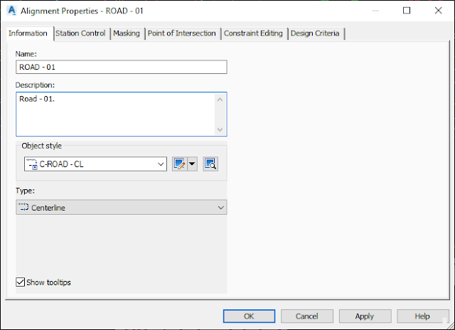
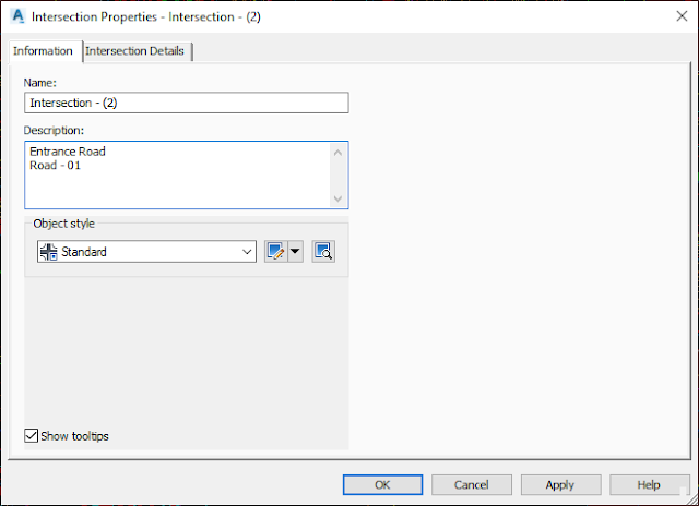
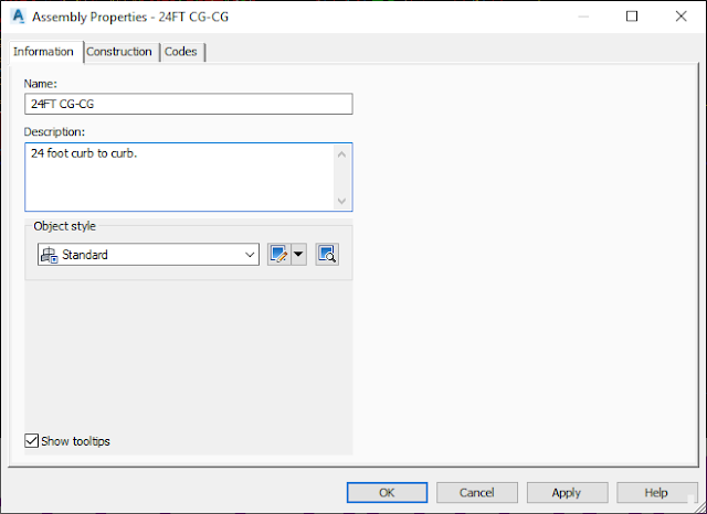
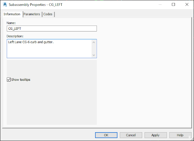
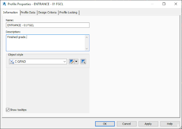
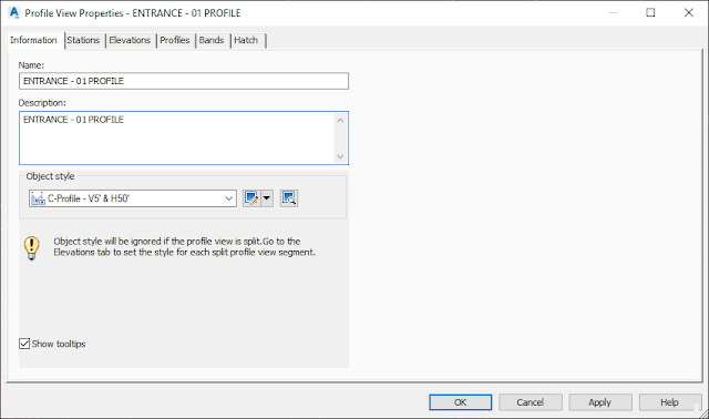
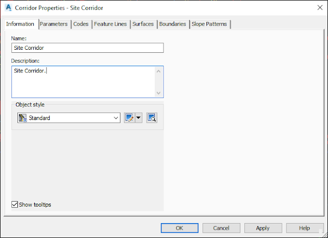
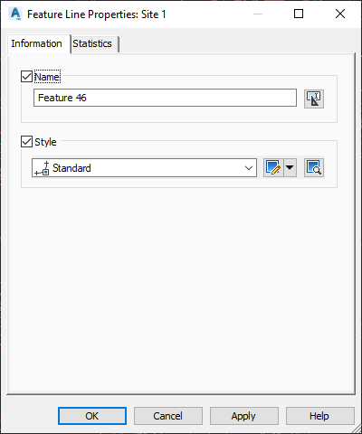
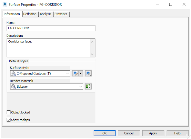
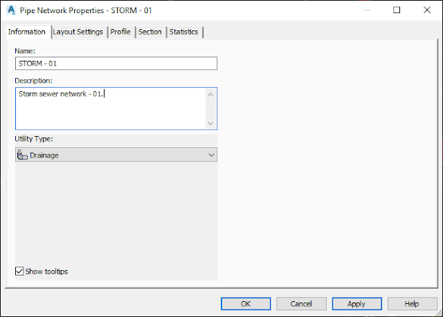
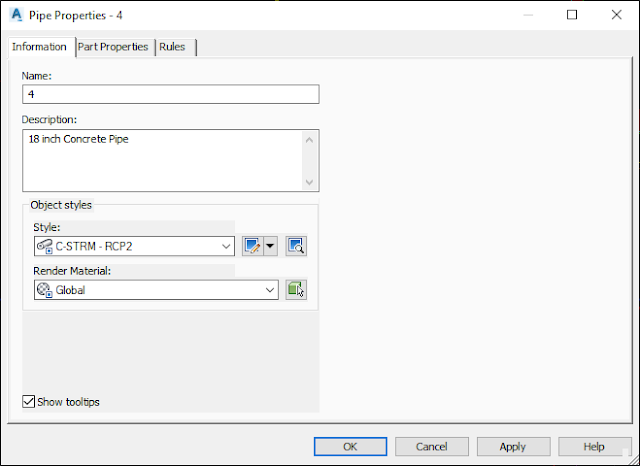
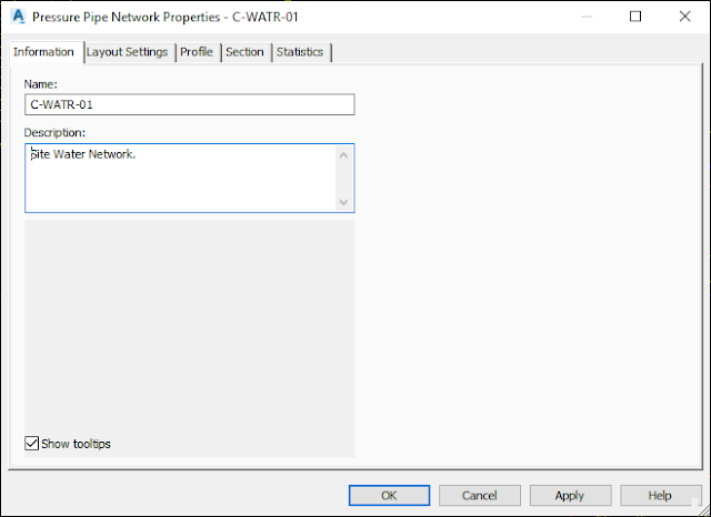
When designing in Civil 3D, naming the Civil 3D objects is beneficial. Rather it is an alignment, corridor, assemblies, surface, pipe network and so on, proper naming will make the workflow much easier for yourself and others on the team to follow and understand throughout the project. I have screen captured several object dialog boxes where names are beneficial. Civil 3D can be set to auto populate names when creating the objects. This can be done in the Civil 3D Command Styles. Names can be set based on your company CAD standards.


Alignment name.


Intersection name.


Assembly name.


Subassembly name.


Profile name.


Profile View name.


Corridor name.


Corridor assembly where names of each component can make building a corridor much easier.


Feature Line name.


Surface name.


Pipe Network name.


Pipe Network pipe part name.


Pipe Network structure part name.


Pressure Pipe Network name.


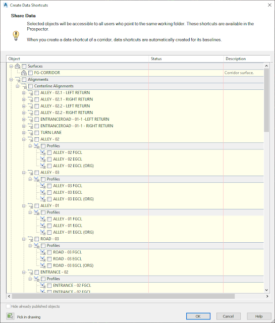
Data Shortcut names.


As projects happen at the speed of light, we tend to put proper organization and how the files are assembled to the side. Proper naming within Civil 3D will save time for yourself and the team during the project but will save a ton of time if the project is shelved.

Tuesday, October 30, 2018

Gaming with the Autodesk AEC Collection Suite

I'm currently building a 3D race track driving SIM using the Autodesk AEC Collection Suite for the Unity 3D game engine.

The suite consist of:
  • AutoCAD Civil 3D
  • Revit
  • Infraworks
  • Navisworks Manage
  • 3D Studio Max w/Civil View
I started the model with InfraWorks to capture the existing track. I then built the high banked track with Civil 3D Corridors. Exported the Civil 3D model to 3D Studio Max via Civil View then exported to an FBX file format. I also modeled other environment assets with AutoCAD and 3D Studio Max.

A workflow is coming soon and maybe to AU2019 if I'm lucky.


Here is the latest progress of the driving SIM recorded from Unity 3D.


Wednesday, August 2, 2017

Export AutoCAD Drawings

Here is a quick tip.

One item I see overlooked when exporting AutoCAD Civil 3D files is the "Selected drawings in source folder" option. Most users export one file at a time. Exporting multiple files will save a lot of time.

Friday, October 28, 2016

OSNAPs Assigned to F-Keys

Do you find yourself not using the F-Keys in AutoCAD? I assigned OSNAPs to my F-Keys. I left F2 and F8 as default.

F1 = Endpoint
F3 = Intersection
F4 = Intersection
F5 = Center
F6 = Perpendicular
F7 = Midpoint
F9 = Insertion
F10 = Tangent
F11 = Quadrant
F12 = Node

Steps
1. Save the F-Keys.cuix to your desktop.
2. Launch AutoCAD.
3. Type CUI in the command line to launch the Customize User Interface.
4. Click the Transfer tab along the top.
5. In the left panel (Main File), expand Keyboard Shortcuts then Shortcut Keys.
6. In the right panel, open the saved F-Keys.cuix.


7. Expand Keyboard Shortcuts then Shortcut Keys.
8. Select the shortcut keys.
9. Drag the shortcut keys to Keyboard Shortcuts\Shortcut Keys on left panel. I placed the keys to the bottom of the list so I can easily find them.


10. Click the Save button on the left panel.
11. Click OK to close the Customize User Interface.

To reassign the OSNAPs with different F-Keys follow these steps.

1. Type CUI in the command line to launch the Customize User Interface.
2. Click the Customize tab along the top.
3. In the top left panel, expand Keyboard Shortcuts\Shortcut Keys.
4. Find the OSNAP F-Keys.
5. Click the desired OSNAP F-Key to change.
6. In the right lower Properties panel, click the button to the right of Key(s).


7. In the pop-up window, press the desired F-Key.


8. Click OK to close the dialog box..
9. Since another OSNAP is assigned with that F-Key, you’ll need to change the other OSNAP with a different F-Key.


10. Click OK to close the notice.
11. Click OK to close the Customize User Interface.

A link to the F-Keys.cuix file.

If you have a hard time remembering which key is which, create a template for the keyboard.

Let me know if you have any questions.