I'm drawing and 3D printing Christmas ornaments. They were modeled in Autodesk AutoCAD and Fusion 360. I used the 0.2mm and 0.4mm hotend assemblies on my Bambu Lab X1 Carbon for printing.
Showing posts with label 3D modeling. Show all posts
Showing posts with label 3D modeling. Show all posts
Tuesday, December 12, 2023
Christmas Ornaments
Tuesday, August 6, 2019
AS319193-L - 3D Modeling with the Best, AutoCAD!
Here is a sneak peak of the type of 3D objects we will create in my Autodesk University 2019 class AS319193-L.
A 3D view of the model.
https://a360.co/2MyWjkW
Labels:
#AU2019,
3D modeling,
AutoCAD,
Autodesk University,
Solids
Tuesday, October 30, 2018
Gaming with the Autodesk AEC Collection Suite
I'm currently building a 3D race track driving SIM using the Autodesk AEC Collection Suite for the Unity 3D game engine.
The suite consist of:
A workflow is coming soon and maybe to AU2019 if I'm lucky.
Here is the latest progress of the driving SIM recorded from Unity 3D.
The suite consist of:
- AutoCAD Civil 3D
- Revit
- Infraworks
- Navisworks Manage
- 3D Studio Max w/Civil View
A workflow is coming soon and maybe to AU2019 if I'm lucky.
Here is the latest progress of the driving SIM recorded from Unity 3D.
Labels:
3D modeling,
3DS Max,
AutoCAD,
Civil 3D,
Civil View,
Gaming,
Infraworks,
Revit,
Unity 3D
Sunday, October 17, 2010
Revolve The Polys!
Polylines can be used to create just about any 3D object. The polylines can either be open or closed. In this tip, I'm going to create a 1" wide by 5" in diameter pulley with groove and flanges.
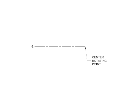
1. Establish a center point of the pulley. This point is the center rotating point of the pulley.
2. Offset the center line to establish the center opening of the pulley. I'm going to create a 1/2" diameter opening so I'll offset the center line 1/4"
3. Establish a center cross section of the pulley.
4. Offset the center cross section line 1/2" to both sides to establish the width of the pulley.
5. Offset the rotating center line 2-1/2" to establish the diameter of the pulley.
6. As for the shape of the pulley, I'm going to leave it to your imagination or specification. This is what I came up with.
7. The shape of the pulley does not have to be closed polyline but I like for it to be.
8. Time to revolve the polyline.
There are a few settings for Revolve.
· ISOLINES = This sets the number of contour lines per surface on objects. I'm going to use the default number.
· MODE = This controls whether the revolve action creates a solid or a surface.
9. Type REVOLVE. I'm going to set the MODE to Solid.
10. Pick the closed polyline pulley shape.
11. Specify the axis start point. I'm going to use the center rotating point of the pulley.
12. Click both ends of the centerline.
13. Specify angle of revolution. I'm going to use 360. This will revolve the closed polyline 360 degrees around the centerline.
We have created a 3D solid pulley.
3D Pulley DWF
Subscribe to:
Posts (Atom)


